|
First Draft - I will correct the torque numbers this weekend. They are not correct at this point. Just want to get tips and feedback at this point. DO NOT USE |
|
|
Quick reference guide |
|
|
|
|
|
Disclaimer: Work on your car at your own risk, this page is a guideline
that I ALONE use. These are things I observed while doing my own
installations. This is dangerous work and ALWAYS use good jack stands and
a hydraulic lift (at the same time) whenever you are working on/under your
car. USE AT YOUR OWN RISK I used the references at the bottom of the page along with tips from Roadfly.org/bmw, Big Coupe Group, Steve Haygood (parts and advice) and my dad as well as years of automobile work to guide me through this process and keep me safe.
|
|
| Tools
Air tools, compressor, 1/2" sockets (17mm,18mm,19mm,22mm,...), 1/4" sockets, 1/2" torque wrench, jack stands, hydraulic lift, Key: <Numbers> reference the picture = <number><#> foot pounds (ft lbs) <Part name><corresponding number in pic> - <part it attaches to> Blue items are book marked to a Glossary at the bottom of the page. Car/parts orientation = From drivers perspective, Left (drivers side), Right (passenger) Tips: Following each pic are some tips to help ease the process |
|
| Table of Contents: Control Arms, Tie Rod Assembly, Drive shaft Assembly, Glossary | |
Upper Control Arm(5) - frame* |
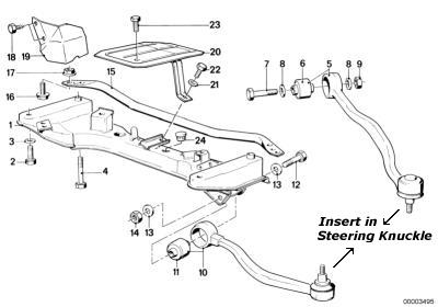 |
| * Remember to torque this end last, one wheel at a time w/ the wheel on the ground (preloading) TOC | |
| Idler Arm bolt #10,8 = 54 Idler Arm - Cntr(11) PS Arm - nut to box PS Arm - Cntr Tie Rod Ends ( both sides) #12,5 = 23-29 Steering Knuckle(1) - Strut mount #2 = 64 |
|
| When replacing the whole assembly I found it easy to attach & torque all items (Idler arm, PS arm, and L & R Tie rod end) that connect to the Center tie rod (Cntr) first then inert the assembly into the frame, inserting but not yet torqueing the PS Arm, insert the idler arm bolt and torque, then follow up by torqueing the PS arm nut. TOC | |
|
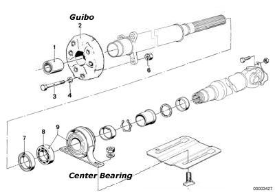
Guibo / Flex-disc bolts |
|
Remove the muffler ( it will be in the way) Clean and grease half shaft splines For the balance of your drive shaft, mark the two half shafts, near the joint, so you can put them back together at the same rotation (spot). Clean rust off all parts that you can see - repaint if needed to keep rust out Preload Center Bearing 1/4" towards transmission Good idea (but not necessary) to change the Center bearing with each Guibo Need 6 new bolts/nuts every time you change your Guibo TOC |
|
|
Glossary
Cntr Center tie rod - Tie rod ends, Idler Arm and PS Arm attach to it and use it as the main directional support for steering Guibo -(Gwee-bow) Flex disc, vibration damping between the transmission and the drive shaft Idler Arm - Attached to the center Tie rod and frame to be a secondary pivot support to the PS arm. PS Arm Power Steering arm - Attaches the Center Tie rod to the power steering box. Str Knkl Steering knuckle - Attaches to strut mount, tie rod ends and control arms attach to it BMW Coupes Manual, Chilton Publications, 1991, San Diego E28 Manual, Bentley Publications, 1994, Livingston, Ohio
|
|
|
USE AT YOUR OWN RISK I DID NOT MAKE YOU READ OR USE THIS - DON'T BLAME ME |
|
|
|
|