Bob Wolbert, K6XX
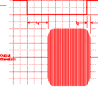
The QSK CW waveform of many rigs is hideous. At high speeds, dots become very light. This is caused by a difference in the time the transceiver takes to switch to transmit mode from receive (RT; t1 in Figure 1) and the time delay between transmit and receive (TR; t2 in Figure 1). If these times were equal, the keyed waveform would be fine. Unfortunately, as the Product Reviews in QST show, nearly all rigs have a much longer RT delay than TR.
Increasing the weighting control on your keyer won't do the job for you--it increases the time of both dots and dashes proportional to keying speed and lower speed CW gets stretched more than fast code. What we really want is a fixed period pulse stretcher. The circuit must be customized for a given transceiver's timing idiosyncrasies.
Further complicating the situation is that the "VOX", or "semi break-in," timing error is usually much shorter than the QSK timing error. This means we need two different pulse stretching periods, or else the mode with less shortening will end up too "heavy".
I had these problems with my TS-950. On a suggestion from Dave, W6NL, I added a capacitor across the key line large enough to compensate for the "VOX" mode timing error. It works with the internal pull-up resistor on the key line to create a simple R-C delay timer; the key quickly discharges the capacitor and pulls the key line low, keying the transmitter. When the key opens, the resistor slowly charges the capacitor before the transmission may end, creating the necessary delay. I unscientifically determined the capacitor size by simply listening to a string of high speed dots and placing various capacitors across the key line until the keying sounded proper.

Now the "VOX" keying was close to perfect. QSK-mode keying also improved a bit, but was still miserable. More drastic measures were required. Measuring the QSK timing with a dual-trace oscilloscope by triggering on the keyer output and comparing this with the RF output envelope, the timing was determined as a 15ms RT delay (t1 in Figure 1) and a 3ms TR delay (t2). This means that the pulse stretching timer needs to add 12ms for perfect code. This represents a dot shortened by 33% at 35 WPM.
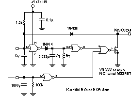
The circuit of Figure 2 provides the needed timing. It is controlled by the rig's front panel "Semi/Full" QSK switch. When OFF, the timer does not operate and passes the keying signal straight through. When ON, the 4011 CMOS logic gate buffers and delays the rising edge of the keying pulse by a fixed amount, independent of keying speed. This delay is set by R1 and C1. Once this time constant was plugged into the circuit, the CW timing sounded (and measured) perfect across the operating speed range.
This relatively simple circuit should be installed inside the rig. Use a temperature-stable capacitor for CV and CT so your keying weight doesn't change as the rig heats up. RT should be in the tens to hundreds of kilohms. If it is not, change the value of CT until it is.

Figure 2. QSK timing compensation circuit mounted inside the rig.
Copyright © 1996, 1998, Bob Wolbert, K6XX

E-mail: Bob Wolbert, K6XX