Bob Wolbert, K6XX
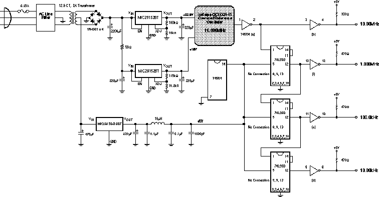
The described project is an oven controlled reference oscillator and marker generator providing output at 10MHz, 1MHz, 100kHz, and 10kHz. It has a self-contained power supply and is intended to run continuously.
The heart of this project is the ovenized reference oscillator module. Two were obtained at a flea market for $5. Two were necessary since no documentation was available and I had to disassemble one unit to see how it worked.
After finding two separate power supplies were needed, and no good indication of what voltage were required, an Internet search was attempted. This located the telephone number of the company, Isotemp, but not any specific information. A call to the company revealed the oscillator was obsolete, but a faxed data sheet was obtained after a bit of persuasion.
The design consists mainly of piecing together the power supply. Three voltages are needed: 13.6V for the oven heater, 10V for the oscillator, and 5V for the logic gates (dividers). The divider chain uses a 74S04 hex inverter for buffering and output drive, and three 74LS90s in a divide-by-ten configuration. Pull-up resistors assist the rising edge of the outputs.
The three voltages are derived from a single center-tapped transformer. The 12.6 VRMS, 2A Radio Shack transformer provides plenty of capacity for the circuit. A bridge rectifier and 2200µF capacitor give about 16.4V of DC input to the MIC29152 adjustable regulator, set for 13.6V of output. The 10V output comes from another MIC29152 regulator. Excess power is dissipated by a 56 ohm, 2W resistor, allowing cooler regulator operation. An interesting configuration is used for the 5V output--notice the input for the MIC29150-5.0 regulator is straight off the center tap of the transformer. Rectification is performed by the same diode bridge that produces the 16.4V raw DC, but the input to the 5V regulator is only half of that voltage, or about 8V. This configuration saves about 2.5W of excess heat generation while adding no extra diodes.
The frequency standard is constructed in an oversized aluminum chassis. A styrofoam block from discarded shipping material was cut to fill about half of the chassis, leaving the rest of the area for the power supply and divider chain. The block was hollowed out to make room for the oscillator module and a styrofoam top cover was fitted with a calibration hole. The aluminum chassis cover has another hole drilled directly above the oscillator module calibration hole for final adjustment.
The transformer and line filter are mounted in the chassis. The bridge rectifier is mounted on top of the 2200µF filter capacitor, which is bracketed to the chassis upside down. Point-to-point wiring runs from the filter capacitor to the regulators, which are mounted directly to the chassis wall--no insulation is necessary, as the regulator tabs are electrically grounded. This way, the chassis provides all required heat sinking.
The divider chain is built "dead-bug" style on a piece of single-sided copper clad PC board material. This technique creates an excellent ground plane. The 5V power supply is RF filtered by a 10µH inductor and ceramic capacitors on the copper clad. Output is delivered to BNC connectors with very short leads and the PC board ground is soldered to the BNC connector lugs.
Crystal oscillators age, with a relatively large frequency shift during "infancy". I let the oscillator run for several months to let this process occur before attempting initial calibration. Not owning an accurate reference (otherwise, why would I build this thing?), I zero-beated the output to WWV/WWVH on the station receiver. Although best resolution would occur by using WWV's 20MHz signal (its highest frequency of operation), 20MHz signal quality was not suitable, and 15MHz was employed. Through estimation of beat frequency, the oven oscillator was running with an approximately 3Hz error. This was very easily trimmed to somewhat less than 1Hz by ear (and S-meter).
One week later the oscillator was rechecked, with any drift below my detection capability.


© 1998, Bob Wolbert, K6XX

E-mail: Bob Wolbert, K6XX