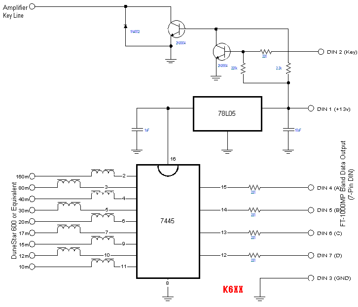
FT-1000MP Band Selection and Amplifier Keying Interface

Bob Wolbert, K6XX
Lucky for me, K2KW needed a safe place to store his FT-1000MP. Upon volunteering for baby-sitting duty, I faced the problem of interfacing the new rig into my (mostly) automated station. Most importantly, the DuneStar bandpass filter bank required control. Eliminating the audible noise and delay problems caused by the amplifier control relay meant adding a solid-state buffer. Since the `MP has an 8-Pin DIN jack on the rear panel that includes both the band control lines and the T/R line, one small box could do the job.
A little experimentation with a voltmeter showed the BAND DATA jack uses 5V logic with the bands encoded in BCD format (see Table 1). Comparing this table with the 7445 BCD to 1 of 10 decoder/driver ICs showed a match. Furthermore, the 30V/100mA rating of the open-collector outputs on the 7445 made the old TTL IC a perfect match. Beside providing a +5V supply, no other active devices are needed for the band interface.


               BAND DATA                  Band
          D     C     B     A
          0     0     0     0               —
          0     0     0     1             160m
          0     0     1     0              80m
          0     0     1     1              40m
          0     1     0     0              30m
          0     1     0     1              20m
          0     1     1     0              17m
          0     1     1     1              15m
          1     0     0     0              12m
          1     0     0     1              10m

Some RF problems in the prototype lead to the 220 ohm resistors in series with each input and the inductors in the output lines. Neither inductor nor resistor values are critical; resistors should not be much larger due to the input current of the 7445 (remember, this is old-style TTL).
My second version uses an IRF510 N-channel MOSFET as the keying transistor. Now, the Key Line output is rated to 100V and 5A, just in case some strange amplifier needs that capability. With a MOSFET output, the 2.2k ohm resistor becomes 22k ohm and the 1N4001 diode is unnecessary. One final option is a switch that disables the DuneStar power when SWLing; even megapower broadcasters are hard to copy when the filters chop them out!

   DIN #       Name             Function
     1         +13V             Aux. power supply output
     2         TX GND           Open collector T/R switch, active low
     3         GND              Ground
     4         BAND DATA A      See Table 1
     5         BAND DATA B      See Table 1
     6         BAND DATA C      See Table 1
     7         BAND DATA D      See Table 1
     8         TX INHIBIT       Handshake*
* Ensures amplifier is ready for RF power. Not used in this interface.

BAND DATA Pin 2, TX GND, is an open-collector output that SHOULD be perfect for driving amplifiers, QSK or otherwise. Unfortunately, Yaesu chose to use a wimpy little transistor that can only handle 15V at 100mA. The 15V is too low for my Alpha, and the 100mA is too marginal for my Ameritrons, especially with the Relay Accelerator circuit employed. Since every rig must operate with every amplifier in case anything breaks during a contest, all interfaces must handle the worst-case combination, meaning the TX GND output needs buffering. NOTE: the TX GND mentioned here is Pin 2 on the BAND DATA connector, not the dedicated phono jack output on the rear panel of the `MP. The phono jack output is from the internal relay and is disabled when the LIN SW is turned OFF; the DIN output remains active regardless of switch setting. The buffer consists of two transistors, each connected as a basic inverter.
The design is nearly complete. The 5V regulator needs two capacitors of noncritical value. Power dissipation for the TO-92 package is 360mW; a bit high. Adding a 100 ohm, ½W resistor in the input lead (between the DIN pin and the capacitor, not between the capacitor and the regulator) reduces IC heating. Or, like me, you could use a TO-220 regulator package instead. The circuit was constructed on perf-board.
This is the best part. Once the interface is built and connected, no user intervention is required. Change the frequency of the FT-1000MP and the DuneStar bandpass filter bank switches automatically. Now turn off the LIN EN switch and run silent QSK with "real" amplifiers. "Baby-sitting" has rarely been this much fun!

Comments? Please send me an e-mail.
E-mail: Bob Wolbert, K6XX
Version 1.1: June 2000
Copyright © 1999, 2000 Bob Wolbert & 26K Engineering